
The picture series I introduced in my last post contains a photograph of a 1930s electronic machine. It seems completely unknown how it was used and if it was a cipher machine at all.
In my last blog post, I reported on a series of photographs showing cipher machines built by US constructor and business man Edward Hebern (1869-1952). These pictures are part of a large collection the Smithsonian Institute recently put into the public domain. Hebern never sold his devices in larger amounts, so he had to give up his business after a few years. Perhaps, the following postcard Hebern had produced found more customers:
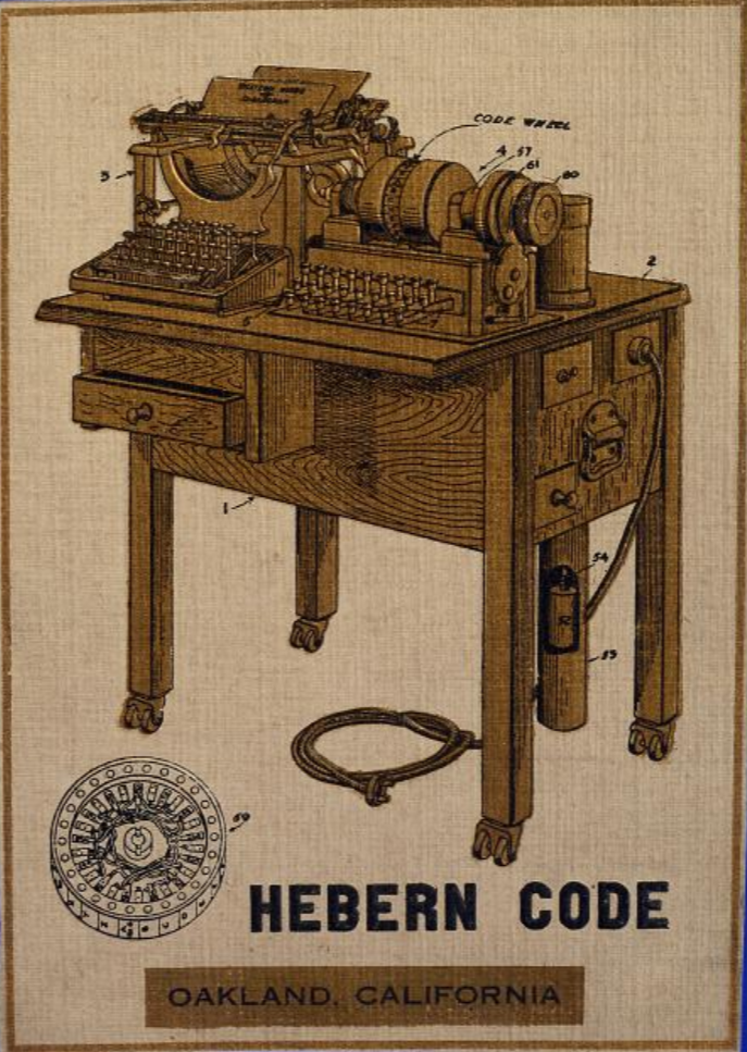
Source: Smithsonian Institution
The vacuum tube machine
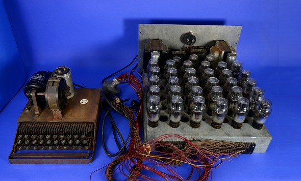
One of the pictures I introduced in my post is the following:
Source: Smithsonian Institution
I originally thought that this is an encryption machine using lightbulbs to display the ciphertext letters, but my readers Richard SantaColoma and Kerberos corrected me. In fact, the glass objects on the right-hand side of the picture are not bulbs but vacuum tubes. This is interesting, as one wouldn’t expect vacuum tubes in a machine that was supposedly built in the early 1920s. In addition, Richard SantaColoma pointed out that the tubes we are dealing with here (Raytheon 6A5G) were introduced only in 1935. They were primarily used as amplifiers, but in this case they may have served as contactless switches.
Here’s the description of the machine on the Smithsonian website (thanks to Ralf Bülow for posting it). To my regret, this text is not very helpful, as it neither provides the year when the device was built nor the way it worked. A wiring diagram would certainly be useful, but is not available on the Smithsonian page, either.
At least, a few more pictures of the same machine can be found in the collection. Here’s a closer shot of the vacuum tubes:

Source: Smithsonian Institution
And here’s a label of a condenser:
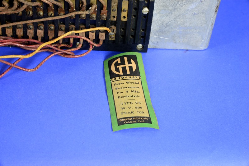
Source: Smithsonian Institution
The following label belongs to the electric motor of the machine:
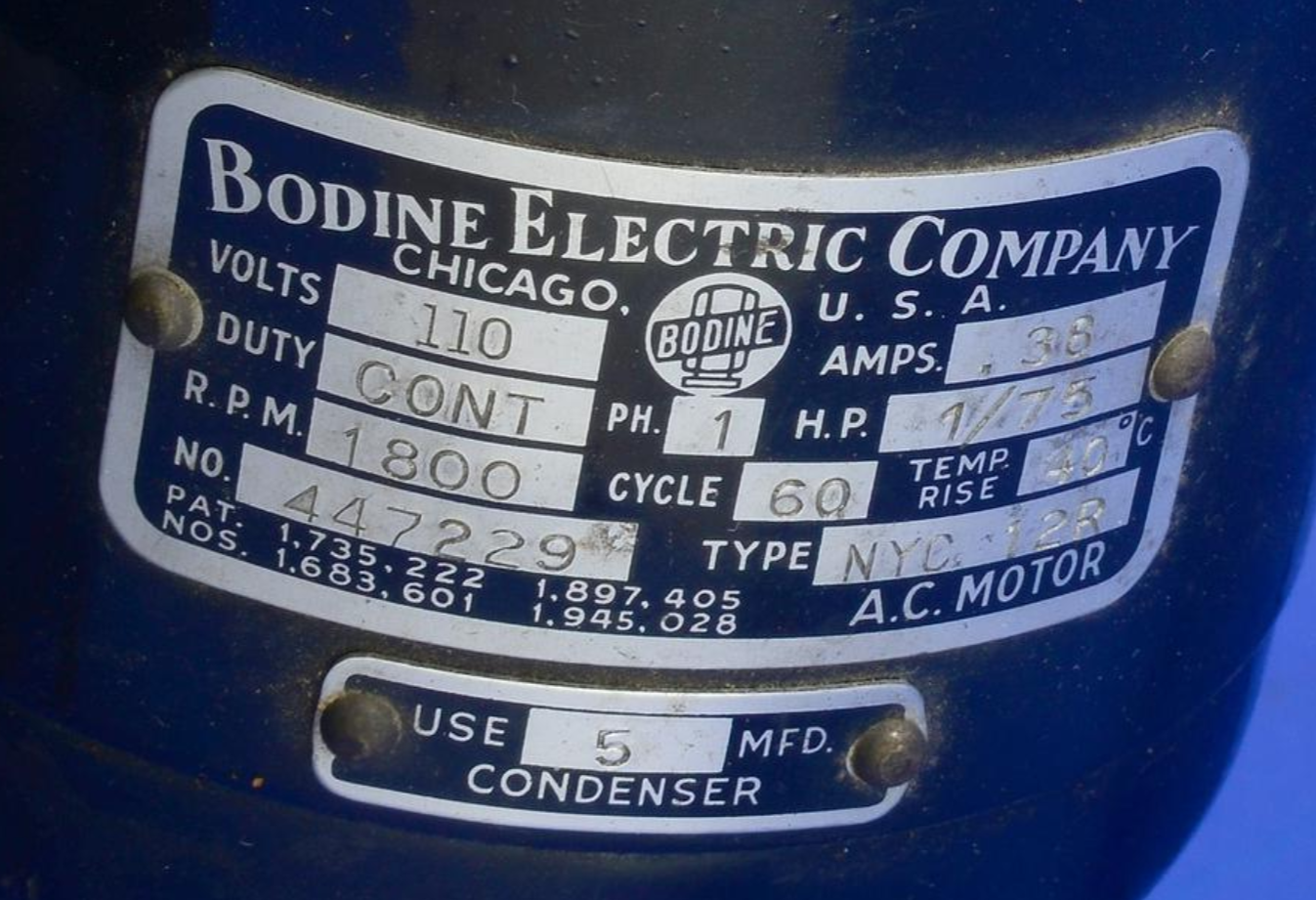
Source: Smithsonian Institution
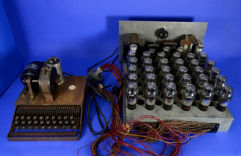
No year is shown, but the patent that is referenced was issued in 1934 (thanks to Gerd for this information). The following picture shows the machine from a different angle:

Source: Smithsonian Institution
Conclusion
As it seems, we are dealing with a machine from around 1935, which means that it was built much later than all other Hebern cryptographs I am aware of. The device involves, among other things, a typewriter keyboard, a motor, and an array of vacuum tubes. So far, I don’t see a proof that this device was really constructed by Edward Hebern, and I’m not sure whether it is a an encryption machine at all. If this design was indeed meant for encryption, it is completely unclear to me how it worked.
The only source about Edward Hebern’s life after 1930 is the article by Glenn Zorpette I already referenced in my last post. Zorpette writes:
He [Hebern] remained active as an inventor, and not just in cryptography. He filed a patent application in November 1938 for a “printing telegraph system,” which converted electrical signals of different time duration to letters or numbers. The signals could be sent by either radio or wire.
To me, this vacuum-tube device doesn’t look like a printing telegraph system, but I may be wrong. Perhaps, a part of the machine is missing.
Can a reader say more about this unusual machine?
Follow @KlausSchmeh
Further reading: Update: A complete (?) list of German cipher machines in World War 2
Linkedin: https://www.linkedin.com/groups/13501820
Facebook: https://www.facebook.com/groups/763282653806483/

Kommentare (16)