A Reddit user has posted photos of an unusual machine, the purpose of which is unknown. Some say it might be an encryption machine. Can a reader tell more about it?

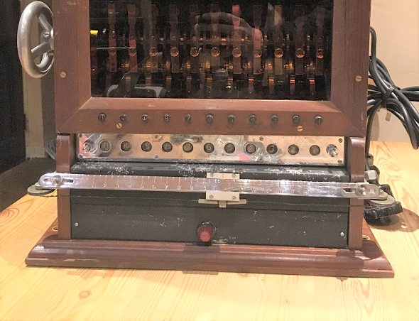
Blog reader Rallinger has, thankfully, made me aware of an interesting discussion going on in the Whatisthisthing group of Reddit. There, a user named Jgbee123 asks: What on Earth is this thing? Here’s the photograph his question refers to:

Unknown-Cipher-Machine-Reddit

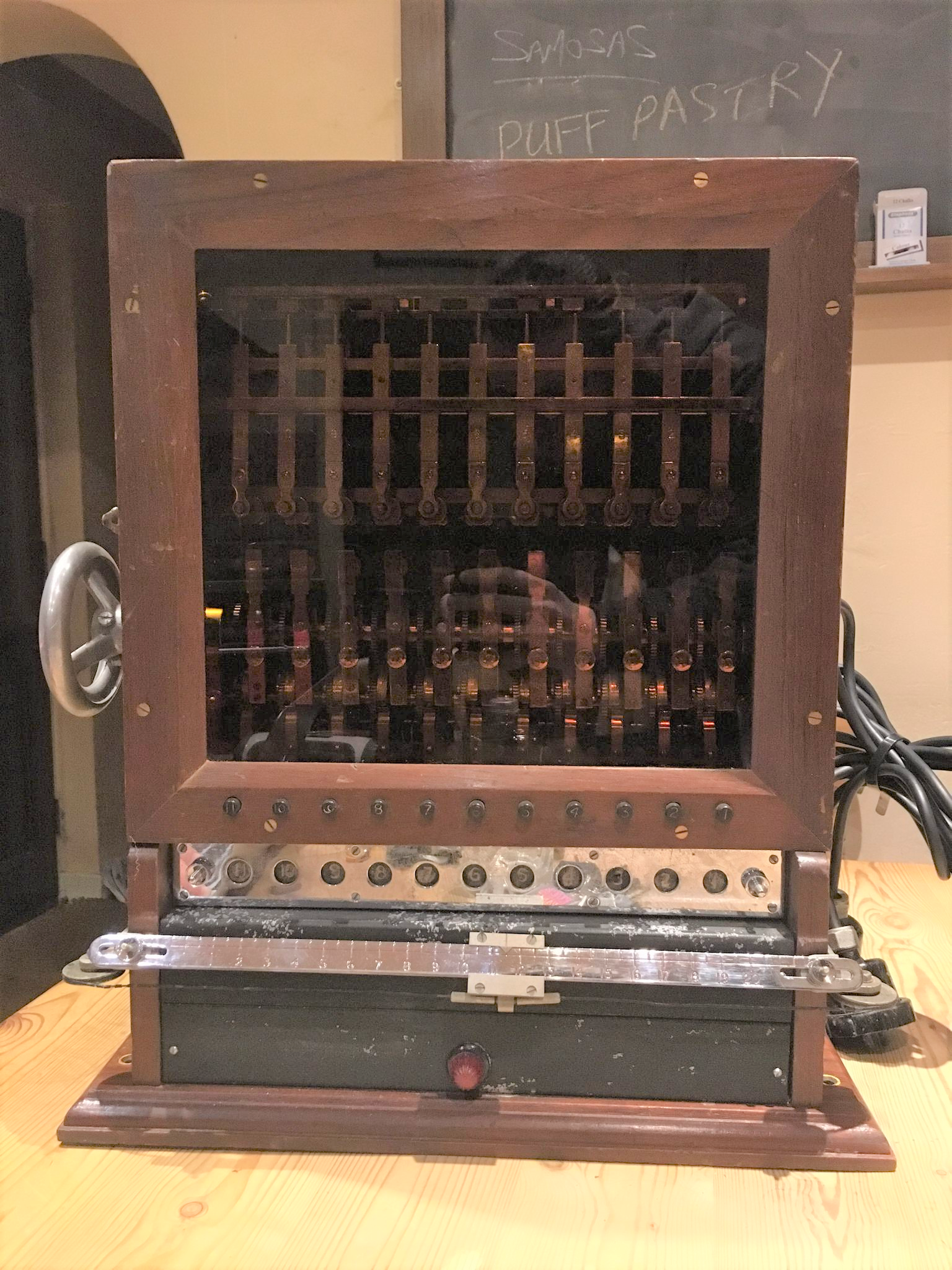
According to the Reddit post, Jgbee123 purchased this item at a junk sale. He thinks it is British, perhaps of naval origin. Here are a few more pictures of this machine.

Meanwhile, a few dozen people have posted comments on Jgbee123’s query. As it seems, none of them has come up with a conclusive answer. Several posters say that this device might be a cipher machine. This is certainly a possibility, though I have never seen anything like this in a cipher machine collection.

One reader writes: “I contacted the curator of the Crypto Museum, and he replied, ‘I have looked at the photographs, but I have absolutely no idea what it is.'” I don’t know, which Crypto Museum this reader means. It could be the Cryptomuseum website (operated by my friends Paul Reuvers and Marc Simons) or the National Cryptologic Museum operated by the NSA. In both cases, the person who replied to this enquiry was certainly competent.

Here are a few other suggestions Reddit users have made:

  • a mechanical computer or adding machine
  • a late model Hollerith machine
  • a remote control apparatus for a naval transmitter of some kind
  • an artillery range calculator
  • an old switchboard

All in all, nobody appears to have a real clue on what this device is about. Can a reader of this blog solve the mystery?


Further reading: An unknown cipher device from Pleidelsheim, Germany

Linkedin: https://www.linkedin.com/groups/13501820
Facebook: https://www.facebook.com/groups/763282653806483/

Subscribe to Blog via Email

Enter your email address to subscribe to this blog and receive notifications of new posts by email.

Kommentare (11)

  1. #1 TrueDan
    Olympia, WA
    24. Mai 2018

    I would be interested in why he thinks this is perhaps of naval origin. It is constructed of wood and I see no corrosion or other damage to the case as I would expect if it was used aboard a ship or a shore station. Is there any type of identification or serial number tag anywhere on the item? There should be a tag of some sort if it was used by the military.

    The upper portion appears to be fixed, although it may allow for calibration of the lower portion. It is difficult to tell from these pictures what happens when the hand wheel is turned. My best guess at this point would be that it was used in a factory to control machinery. Perhaps it was used to control a weaving machine or a milling machine.

  2. #2 Tony
    24. Mai 2018

    Looking especially at this photo https://i.imgur.com/8VS6BFb.jpg
    seems to me fundamentally as 11 electromechanical relays (take a look for comparison to the relay photo on this page https://www.glolab.com/relays/relays.html showing the copper wire coil) and that idea of 11 circuits being electrically controlled by those relays is supported by the (1-11) numbered connector on the left side, shown here
    https://i.imgur.com/iRmwDmk.jpg
    Again, the numbers simply run 1-11 as also shown in this photo https://i.imgur.com/dEzm5Zd.jpg
    Tony

  3. #3 Rich SantaColoma
    https://proto57.wordpress.com/
    24. Mai 2018

    My (very tentative) guess is that this is meant to control multiple electric locks, and give feed back to their state. This would be done in a prison, most likely…

    On the one hand, all locks could be opened or closed with the wheel on the left, as all cams to the bottom switches seem to be in the same orientation.

    And if one where to lock all the locks, the solenoids at the top could give feedback on their “state”… that is, if the door was open, or jammed, the appropriate light could light (or not, depending on how it would be wired), telling the controller that the doors are not all currently lockable…

    So my guess is a door lock controller at a prison.

  4. #4 Marc
    24. Mai 2018

    Ich glaube, dass man auf der linken Seite über dem Rad einen Stecker reinstecken muss. Das mit 1 bezeichnete Loch ist größer als die anderen. Dies soll wohl verhindern, dass ein Stecker falsch herum eingesteckt wird. Evtl. muss dieses Gerät hier über ein Verbindungskabel mit einem anderen Gerät verbunden werden, damit es funktioniert.

  5. #5 Rich SantaColoma
    24. Mai 2018

    I did a search for: prison electric door lock control panel

    And didn’t see anything exactly like the device here. But there are many different types. Here is one from 1930… the doors are closed and opened manually, with the crank, but you can see dual rows of switches to electrically control the locks:

    https://www.correctionhistory.org/html/chronicl/nycdoc/1930s-Rikers-aerial/lock-system1a.jpg

  6. #6 Larry McElhiney
    Carmel, Indiana
    25. Mai 2018

    I notice the lower number plate on the front with it’s two knurled nuts for easy removal. Possibly a way to configure the number relationship between the two sets?

    24DDC is probably a control line output voltage, with the 110VAC driving the internals.

    For some reason, visibility of the front interior was important. Maybe this was built as a job aid for training to use/maintain an installed system.

    It definitely has the look of a one-off device.

  7. #7 Alex Ulyanenkov
    25. Mai 2018

    Looks like a machine to control the status of partitions or doors – open/closed, as well as to control the current position (width of opening – because of that we see line with slider in front of the tool) for each partition or door during it movement.

  8. #8 Gerd
    25. Mai 2018

    The idea of controlling 11 doors is good, I think. However the handle on the left side is attached to a cam shaft that allows all signals to be given simultaneosly when turning it. This might be the contol panel for a starting machine for horse races, allowing 11 start boxes to be controlled. The horizontal scale on the bottom might count the leaps?
    Just a guess…
    Gerd

  9. #9 joe
    Berlin
    26. Mai 2018

    Guten Tag,

    wie sieht es denn aus wenn man mal den Stromlaufplan aufnimmt!

  10. #10 Rainer Glaschick
    Paderborn
    28. Mai 2018

    As there is not yet anyone who has seen such a device before, we should stop speculating and instead collect what we can see from the pictures and what are the open questions.

    If the poster of the pictures (jgbarefoot) in interested, a wiki page or similar could be set up and a group of people found that would like to evaluate instead of speculate.

    My first notes would be:

    There are 11 vertical units with 2 solenoids each.

    On the right side there is a power supply for 110V and 24V.
    On the left side there is connector for 11 wires, that go into the slightly diagonal tube on the back and are connected to the columns.
    There is also a handwheel that drives simultaneously gear for each of the 11 columns.
    And a switchbox with a 3 jacks.

    A front door can be opened and has 11 keys that can give contact from a common wire connected in the hinge to the lower contacts of the columns.

    A slider in the lowest part has 20+ positions marked and also the halfs. It seems to be movable in smaller steps.

    The top row of magnets can move a lever, which is hold (e.g. no. 8) in the top. Unclear how it is released. Also unclear, if the lower end is a spring or a contact.

    Below the door keys and above the slider are 11 windows with numbers behind; there may be lamps behind.

    The keys in the front door do probably give a signal, as the contacts may be connected to a curved wheel driven by the gears, but these seem to be all in a non-contact position.

    The (mechanical) effect of the lower solenoids is unclear from the pictures.

  11. #11 Joe
    Berlin
    28. Mai 2018

    Gutes “reengineering” ist der Weg zur Erkenntnis.