
Edward Hebern was a bustling, yet successless constructor of cipher machines. The Smithsonian Institution has put a number of photos of these devices into the public domain.
Edward Hebern (1869-1952) was a notable figure in the history of cryptology. After a deprived youth, he lived the life of a farmer in California, before he had to serve a prison sentence because of horse thievery. While in jail, around 1908, he had the idea of constructing an electromechanical encryption machine, which led to his first patent being granted in 1914. Hebern built the first rotor-encryption machine, years before the Enigma came to the market with a similar design.
Edward Hebern
Hebern was apparently a good craftsman and did a good job in convincing others of his ideas. He sold about a million dollars’ worth of stock in his company Hebern Electric Code and built an impressive neogothic factory building in downtown Oakland (I had the pleasure to visit this place in 2016).

Source: Schmeh
This three-story structure was built to accommodate 1,500 workers and included a luxurious office for Hebern. Today it is located in Oakland’s chinatown, hosting, among other things, a juice and smoothie store.
However, Hebern, who had never attended a university, was not a particularly good businessman. In addition, the demand for encryption machines was still low in the 1920s, which led to neither Enigma inventor Arthur Scherbius nor Boris Hagelin, who later became the most successful crypto device producer ever, nor “cipher aristocrat” Alexander von Kryha to never make substantial revenue from cipher technology in those days. Edward Hebern’s company inevitably went bancrupt and Hebern had to retire from the crypto business.
Today, Edward Hebern’s encryption machines are sought-after collectibles. I know of about ten devices of this kind to exist, which makes even the Enigma (some say that about 1,000 specimen have survived until today) look like bulk good.
Here’s the only article about Edward Hebern I’m aware of.
The Smithsonian pictures
My friend Tobias Schrödel, known as comedy hacker, crypto book specialist and encrypted postcard collector, has recently pointed out to me that the Smithsonian Institution has put 2.8 million images in the public domain. Tobias suspected that this huge collection includes crypto-related material, and he was right. When I searched the Smithsonian website for items tagged “cipher” or “encryption”, I immediately received a few interesting results. Most of all, I found dozens of photographs of Hebern encryption technology I had never seen before. In the following, I’m going to introduce a few of these pictures.
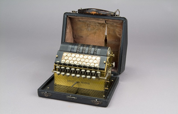
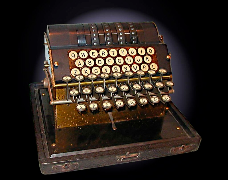
An early Hebern prototype. The lamps that indicate the cipher letters are still separated from the keyboard. Source: Smithsonian Institution
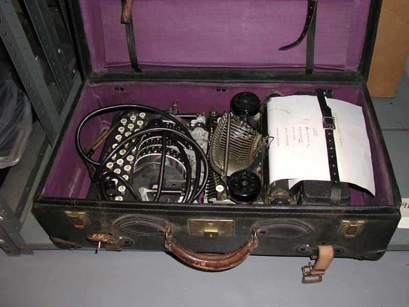
This Hebern machine, placed in a purple-lined suitecase, was certainly not designed for military customers. Just like the Enigma and the Kryha machine, the Hebern devices were offered to civil customers such as banks or international corporations, but completely failed on this market. Source: Smithsonian Institution
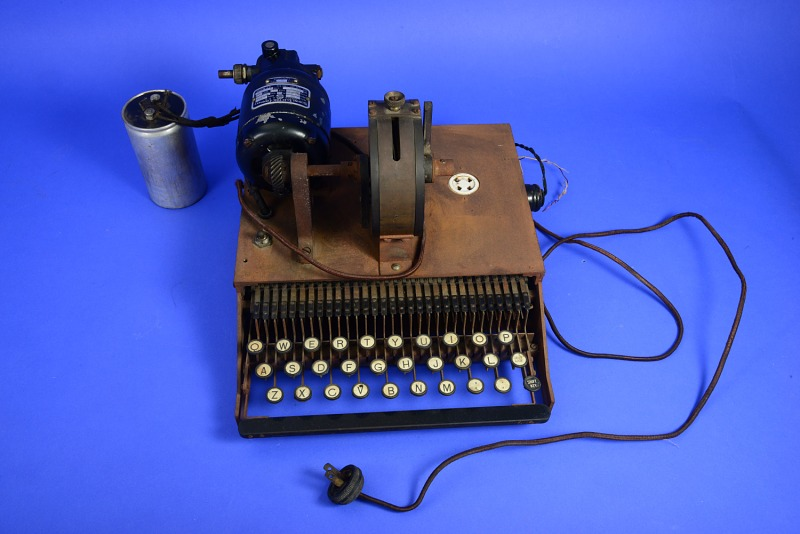
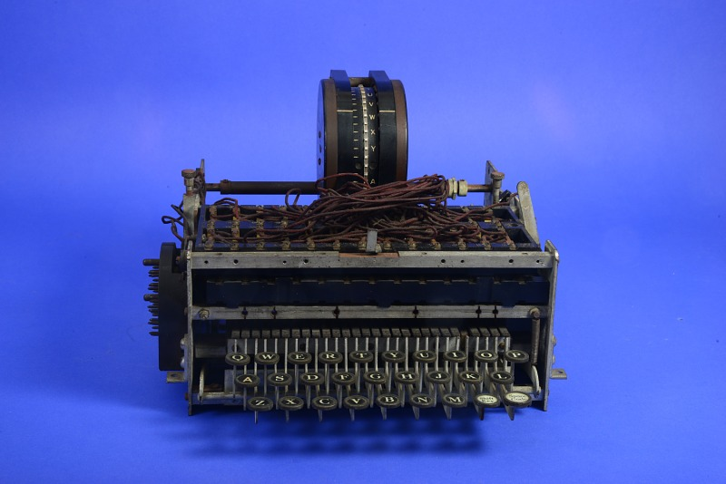
This Hebern machine worked with only one rotor (which is missing here). Later designs had up to five rotors. Source: Smithsonian Institution
Another one-rotor Hebern model, probably made around 1920. Source: Smithsonian Institution
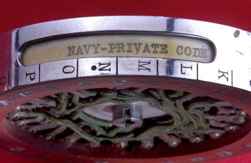
Edward Hebern expected to sell a large quantity of his machines to the US Navy. This never happened. Only in the 1930s, the US miltary introduced rotor machines, when Hebern was long out of business. Source: Smithsonian Institution
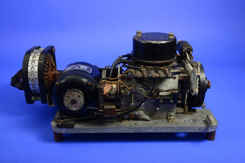
One of Hebern’s many one-rotor designs. A far as I know, the evolution of Hebern’s machines has never been researched. Source: Smithsonian Institution
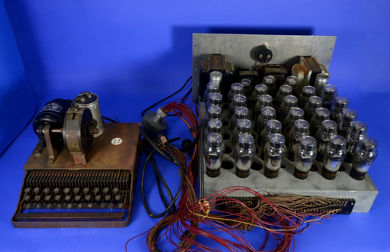
This five-rotor encryption machine is one of Hebern’s most advanced designs. Most or even all of the Hebern machines still existing today are unique; I have never seen two of the same kind. Source: Smithsonian Institution

All of Hebern’s later models were based on wired rotors. This method proved extremely successful in the 1930s, but Hebern, who was active ten years earlier, never sold his designs in notable amounts. Source: Smithsonian Institution
Thanks to Tobias for informing me about this great picture collection and thanks to the Smithsonian Institution for putting it into the public domain.
Follow @KlausSchmeh
Further reading: Hidden message discovered on tombstone of famous cryptologist couple
Linkedin: https://www.linkedin.com/groups/13501820
Facebook: https://www.facebook.com/groups/763282653806483/

Kommentare (15)